|
by Andrei Gradinari
Sometimes there is a need to show what is inside of an object. For example, let's say you want to see what our planet looks like on the inside. I'm going to show you how to cut a piece out of it.
What we have is shown in Figure 1a, and what you want to have is shown in Figure 1b:
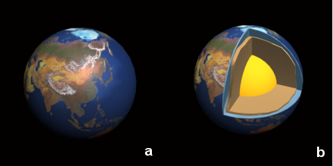
Figure 1: (a) Earth model, (b) desired result
I'll explain how to implement this in real time.
First of all, you need 3 meshes. One will represent the Earth's core, the second will represent the earth's mantle, and the third will represent the Earth's surface, as shown in Figure 2:
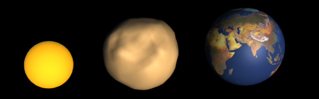
Figure 2: The three meshes used to render the earth.
Let's render the earth meshes with a single arbitrary clipping plane applied. Figure 3 shows the results you'll get. As you can see, OpenGL just clips the geometry and doesn't show the clipping edges. But there is a way to make OpenGL to do this.

Figure 3: Arbitrary clipping plane applied to the earth models.
What you will do is render the mesh with a single clip plane enabled. Then you'll render the mesh's clip edges. OpenGL doesn't know what a clip edge is, so you'll have to "explain" it to OpenGL.
Finding the Clip Edges
So, how do you find the clip edges? Let's look at a surface mesh clipped by an OpenGL clip plane.
Figure 4a shows the front facing polygons which survive the clipping process. Figure 4b shows the back facing polygons which survive the clipping process (OpenGL culled them and thus they weren't rendered in Figure 4a).
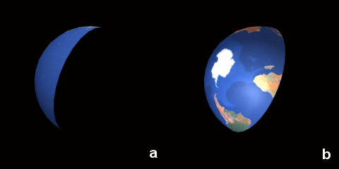
Figure 4: Front (a) and back (b) faces after clipping.
There is one interesting thing about these images. Suppose you use these images to create a pixel mask where the mask is 0 where the original image is black and 1 otherwise. If you then subtract the mask created from the front-facing image (mask A) from the mask created from the back facing image (mask B), you'll get a new mask (mask X) that represents the area where the clip edge would be. This is illustrated in the following equation and in Figure 5:
mask X = mask B - mask A
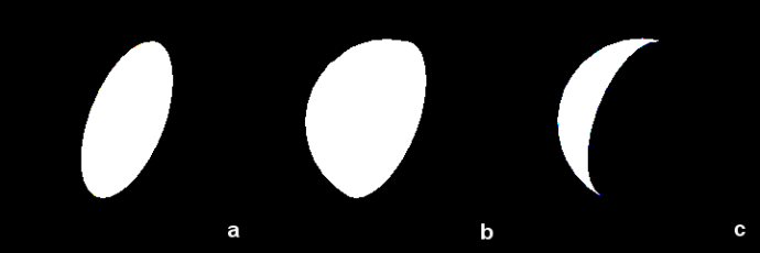
Figure 5: Constructing a pixel mask.
The next step, then, is to figure out how to build these two masks, and then implement per pixel subtract. This is where OpenGL's stencil test becomes useful.
Using the Stencil Buffer
If you already familiar with using the stencil buffer, feel free to skip to the next section. Otherwise, I'll provide a quick overview.
Enabling stencil testing adds an additional condition in the fragment pipeline. If stencil testing is enabled, after passing the depth test each fragment will then go through the stencil test. If the fragment passes the stencil test it will be written to the frame buffer, otherwise it will be discarded. The stencil test is very similar to the depth test. In both cases you have a per fragment test used in conjunction with a dedicated buffer. The main difference between the two is the test functions.
OpenGL provides set of functions and constants for setting up stencil test parameters. I'll provide a short overview of them.
glClear(GL_STENCIL_BUFFER_BIT);
This clears the stencil buffer.
glEnable(GL_STENCIL_TEST);
glDisable(GL_STENCIL_TEST);
These are used to enable or disable stencil testing in OpenGL.
void glStencilFunc(GLenum func, GLint ref, GLuint mask);
This specifies the stencil test function. func can be GL_EQUAL, GL_LESS, GL_GREATER, GL_ALWAYS, GL_NEVER, GL_LEQUAL, GL_GEQUAL, or GL_NOTEQUAL.
ref is used to provide a reference value. The value in the stencil buffer at the current location is compared against the reference value (using the stencil test function) when deciding if the test passes or not.
mask is used to set a mask which is applied to both the reference value and stored stencil value before the comparison is performed.
void glStencilOp(GLenum fail, GLenum zfail, GLenum zpass);
Each of these parameters can be one of the following: GL_KEEP, GL_ZERO, GL_REPLACE, GL_INCR, GL_DECR, GL_INVERT, GL_INCR_WRAP, or GL_DECR_WRAP.
fail specifies the action to take when the stencil test fails.
zfail specifies the action to take when the stencil test passes, but the depth test fails.
zpass specifies the action to take when both the stencil test and the depth test pass, or when the stencil test passes and either there is no depth buffer or depth testing is not enabled.
glStencilMask(GLuint mask);
This controls the writing of individual bits to the stencil buffer bit planes. This won't be used in the demo.
Setting Up the Stencil Buffer to Find the Clip Edge
Let's look at how to set up the stencil test to find the clip edges:
// Clip plane setup
vec3 verts[4] = {...};  // quad, defining our plane
GLdouble *eq;
get_plane_equation(verts[0], verts[1], verts[2], eq);
GLuint MY_CLIP_PLANE = GL_CLIP_PLANE0;
glEnable(MY_CLIP_PLANE);
glClipPlane(MY_CLIP_PLANE, eq);

//****** Rendering the mesh's clip edge ****//
glEnable(GL_STENCIL_TEST);
glClear(GL_STENCIL_BUFFER_BIT);
glDisable(GL_DEPTH_TEST);
glColorMask(GL_FALSE, GL_FALSE, GL_FALSE, GL_FALSE);
Besides enabling stencil testing, I also disable depth testing and writing to the color buffer. This is because only the stencil buffer needs to be updated at this point, and depth testing is not necessary.
Instead of building two masks and then subtracting one from the other, I'll set the stencil buffer operation to increment when rendering back-facing polygons and decrement on front-facing polygons. This will result in the desired mask (mask X from above) stored in the stencil buffer after 2 rendering passes:
// first pass: increment stencil buffer value on back faces
glStencilFunc(GL_ALWAYS, 0, 0);
glStencilOp(GL_KEEP, GL_KEEP, GL_INCR);
glCullFace(GL_FRONT); // render back faces only
EarthSurface->Draw();
// second pass: decrement stencil buffer value on front faces
glStencilOp(GL_KEEP, GL_KEEP, GL_DECR);
glCullFace(GL_BACK); // render front faces only
EarthSurface->Draw();

glEnable(GL_STENCIL_TEST);
glClear(GL_STENCIL_BUFFER_BIT);
glDisable(GL_DEPTH_TEST);
glColorMask(GL_FALSE, GL_FALSE, GL_FALSE, GL_FALSE);
If you're using OpenGL 2.0 or higher, this can be reduced to a single pass using two-sided stencil.
After this step is complete, the desired mask is the set of points in the stencil buffer with values greater than zero. The next step is to render a plane that represents the clip edge (Figure 6) to the color and depth buffer using the stencil test.
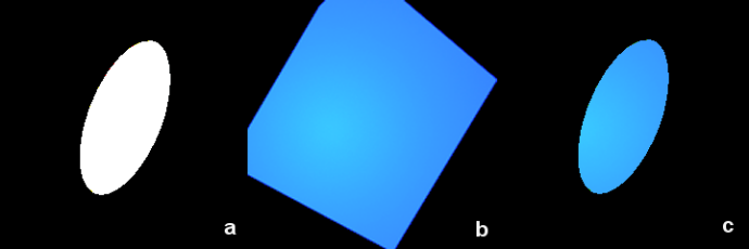
Figure 6: Masking the plane image.
// drawing clip planes masked by stencil buffer content
glColorMask(GL_TRUE, GL_TRUE, GL_TRUE, GL_TRUE);
glEnable(GL_DEPTH_TEST);
glDisable(MY_CLIP_PLANE);
glStencilFunc(GL_NOTEQUAL, 0, ~0);
// stencil test will pass only when stencil buffer value = 0;
// (~0 = 0x11...11)
glBegin(GL_QUADS); // rendering the plane quad. Note, it should be big
                   // enough to cover all clip edge area.
for(int j=3; j>=0; j--) glVertex3fv(verts[j]);
glEnd();
//****** End rendering mesh's clip edge ****//
Now that the clip edge image has been rendered to the color and depth buffers, the final step is to render the earth surface mesh with the stencil test disabled.
//****** Rendering mesh *********//
glDisable(GL_STENCIL_TEST);
glEnable(MY_CLIP_PLANE); // enabling clip plane again
EarthSurface->Draw();
The final result is shown in Figure 7a:
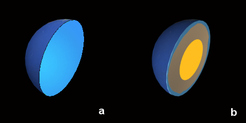
Figure 7: Final result with one clipping plane.
That's the basic technique, but I want to take this a step further and be able to produce real "slice" looking images like one shown in Figure 7b. To do this you just need to loop as follows:
// suppose earth mesh object's pointers are stored in m_pEarth array
// in this order: 0 - Core, 1 – Mantle, 2 - Surface

for(int i=0; i<3; i++)// render Earth meshes
{
   BIND m_pEarth[i] MATERIAL
   RENDER m_pEarth[i] clamp edge
   RENDER m_pEarth[i] mesh
}
Note the order in which I grouped the Earth meshes. The order is important, since you need to render the smallest mesh first, and the biggest last. This is because all geometry is clipped by a single clip plane, and it is very likely that clip edges overlay. You need the smaller edges to be rendered before the larger ones and thus occupy the overlapping area with its depth and color. Then, when the larger mesh's clip edges are rendered to the overlapping area, the depth test will fail and the color from the smaller mesh will be preserved. Just make sure that the depth function is set to GL_LESS (the default value).
Advanced Pie Slicing
If you're still not satisfied by what you can do with clip planes and the stencil buffer, let's see how to cut a piece out of the Earth not just slice it in half.
To do this, you need to setup three clip planes (in this case corresponding to the xy-plane, yz-plane, and xz-plane), and then render the scene three times, each time enabling a different clip plane.
// setup clip planes
vec3 verts[3][4] = { // 3 sets of 4 points. Each set defines a plane. };
GLdouble eq[3][4]; // 3 plane equations
for(int k=0; k<3; k++)
   get_plane_equation(verts[k][0], verts[k][1], verts[k][2], eq[k]);

for(int k=0; k<3; k++) // render 3 times for 3 different clip planes
{
  MY_CLIP_PLANE = GL_CLIP_PLANE0 + k;
  for(int i=0; i<3; i++)
    // render Earth meshes
}
Figure 8 illustrates how this works.
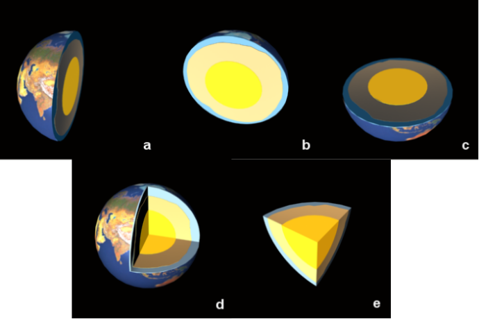
Figure 8: Removing a slice from the Earth in 3 passes.
In Figure 8a you see the scene rendered three times without clearing the frame buffer between passes. Each time a different clip plane is enabled. You may wonder why you can't use a single rendering pass with all three clip planes enabled. Figure 8b shows what the results of that would be. This happens because the resulting clipping region is the intersection of the defined half-spaces; it is always convex. Thus, as a result you will get a convex slice. Image 8a shows the non-convex shape built in three passes.
Everything seems to be done, but the image still doesn't look quite right. It would look a little better if the core mesh weren't clipped and the mantle mesh were rendered with a little offset added to the clip planes.
The easiest way to render the core mesh without clipping is to just draw it after the rest of the mesh has been clip. So the last bit of the previous pseudo-code would become:
for(int k=0; k<3; k++) // render 3 times for 3 different clip planes
{
  MY_CLIP_PLANE = GL_CLIP_PLANE0 + k;
  for(int i=1; i<3; i++)
    // render Earth meshes
}
m_pEarth[0]->Draw() // draw core mesh
Notice that the inner loop now starts at 1 since there is no need to draw the clipped core mesh. Figure 9a shows the results of this.
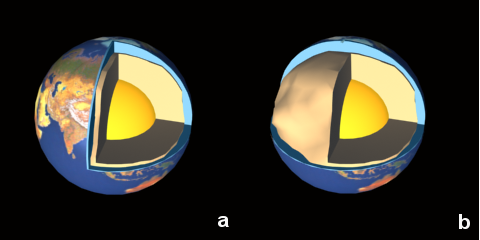
Figure 9: Final Earth images.
You can experiment with enabling or disabling particular clip planes for individual meshes. For example, in Figure 9b, you can see the results of disabling one clip plane for the surface mesh. To do this, just add this condition at the beginning of inner loop:
if(k==1 && i==2) continue;
|